Posted on Leave a comment

Everything You Need to Know about Capturing Full Arch Impressions and Designing / Fabricaing All on X Restorations

In this article we detail everything you need to capture to design and all on x type of restoration so you can quickly print a prosthesis and deliver it to your patient as quickly after surgery as possible.  We think it is best to start with the end in mind and work backwards to the models you need to capture.

Models Needed to Design

These are the models you need to bring into exocad per arch.  Of course, you can bring in more information into the equation if you chose to:

  • Tissue scan (ideally when sutured and not a bloody field). This is usually captured with an intra-oral scanner. Some take an alginate of the arch and scan it with a desktop scanner.
  • Implant locations, which are the multi-unit abutment margins.  These are captured in a variety of ways, all of which have to address the limitations of scanning edentulous flat and symmetric surfaces which introduce Veersing Errors.  These options include extra-oral photogrammetry, intra-oral photogrammetry, and/or implant suprastructures that reduce or eliminate scanning errors, like the Scan Ladder, io connect from TruAbutment, etc…
  • Preop Scan, or more ideally a wax up scan to the correct vertical dimension
  • A designer also ideally would want the opposing model and buccal bites as well.

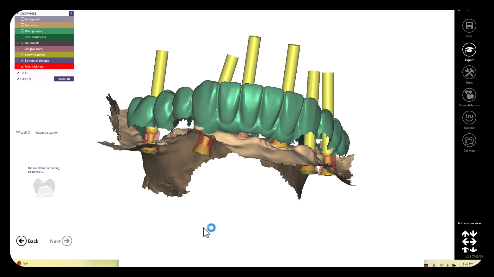
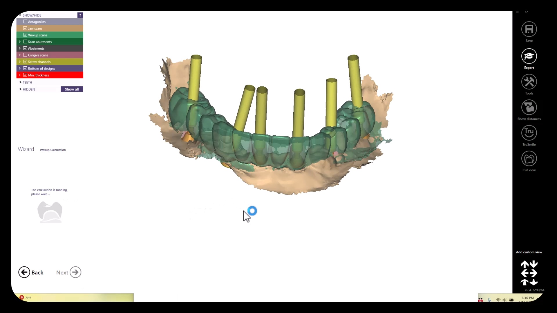
All of these models need to be properly related to each other which is an endeavor in itself.  All of the models listed above are also disciplines of their own and many chapters could be devoted to each topic. Assuming you have this information imported into CAD software correctly, you can design the temps very quickly and get them into the printer for a temporary
video
play-rounded-fill
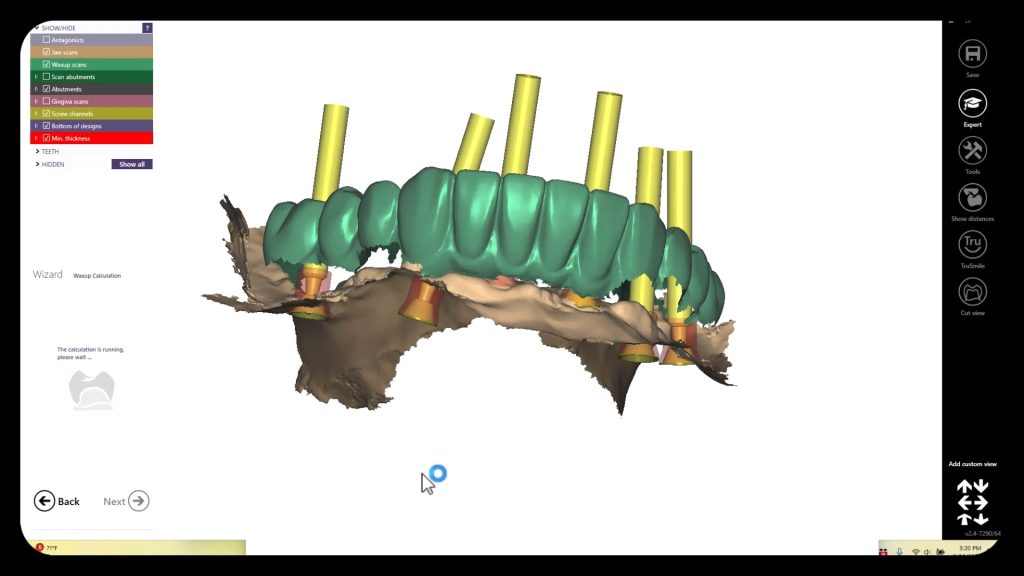
Rapid Design of All on X with exocad

Merging Models to Each Other

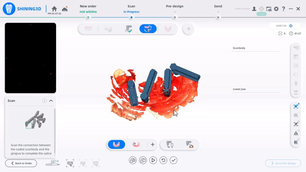
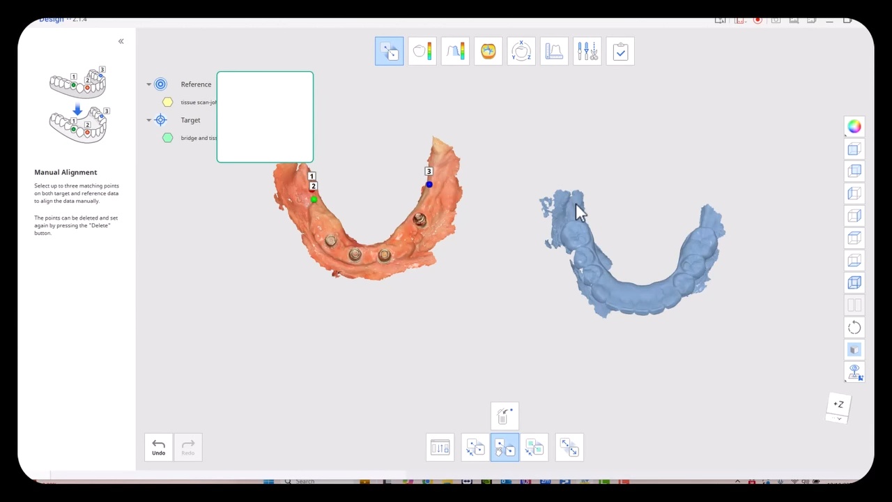
The traditional approach to these cases required a model of the arch with some suprastructure that could be used to relate it to the photogrammetry scan.  This process can be quite arduous and involves lots of steps.  Other current systems, like the Shining Elite allow you to merge models in the native scanning software.  Alternatively, you must make sure you have common stitching abutments to related models to each other in CAD software.  You can use common landmarks that are found in both models to accomplish this like in this demonstration
video
play-rounded-fill
Using Common Landmarks to Relate Models to Each Other

Managing Surgical Cases Where Stitching Landmarks are Removed to Accommodate Space for the Prosthesis

The approach to these get much more complicated when you don’t have those landmarks available to you from one model to the next, usually because the they have been surgically removed. You must:

  • Capture the pre-op or wax up and relate it to the tissue scan
  • capture the tissue scan and relate it to the implant location models.

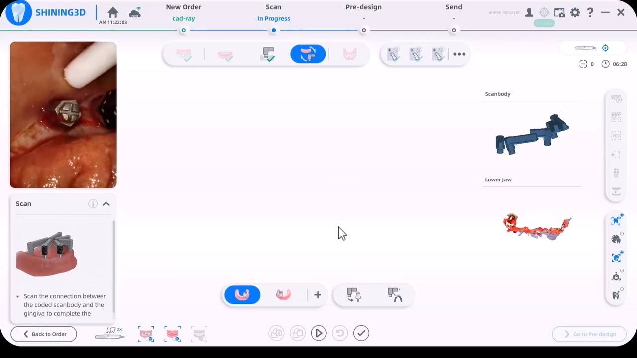
One way to do this is to place arch trackers in areas away from the crucial areas of the arch, namely the retromolar pad area on buccal to the mental foramen.  The Shining Elite Scanner allows you to do this in their own native imaging software. In the first video you will see how the arch tracker allows you to relate the iPG scans with your tissue scans.
video
play-rounded-fill
Arch Tracker used to Relate the iPG and Ios Models to each other

You have to leave the arch tracker in place from the very beginning to the very end. If possible, we recommend you remove them only after you have placed the temporaries as it leaves you a back up in case something goes awry in the process.  You will use it to relate the preop to the tissue to the iPG models.

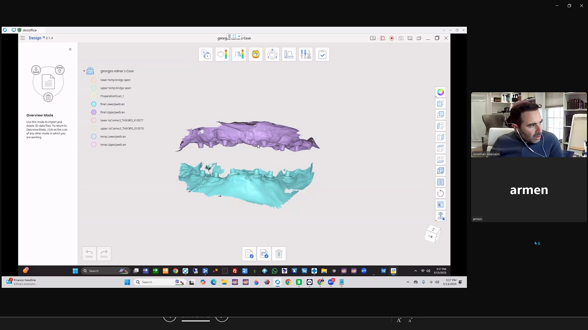
Alternate methods include using proprietary material from sources that are very well versed in this matter, like Jonathan Abeneim’s Excel Protocol, which he highlights in this webinar.  He used his THS caps to not only related these models to each other but also perfectly mount your models to the opposing arch
video
play-rounded-fill
THS Caps by Dr. Johnathan Abeneim
Posted on Leave a comment

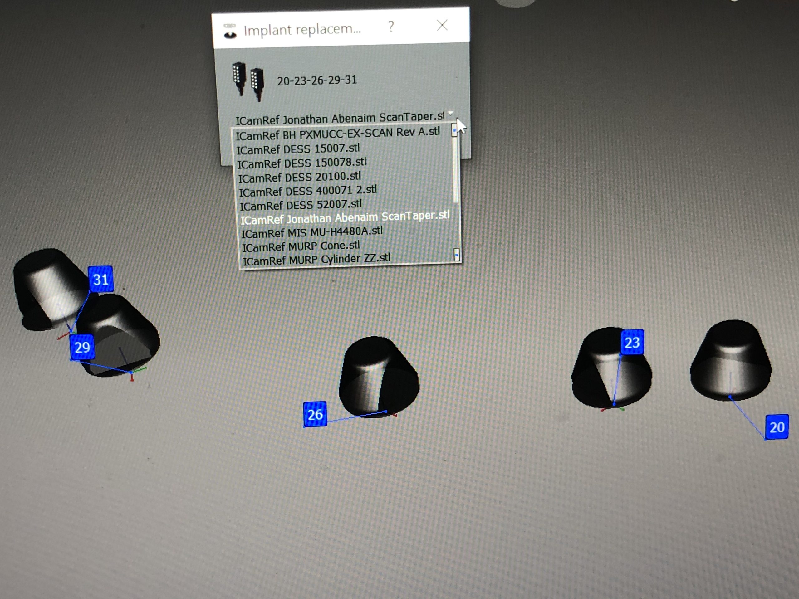
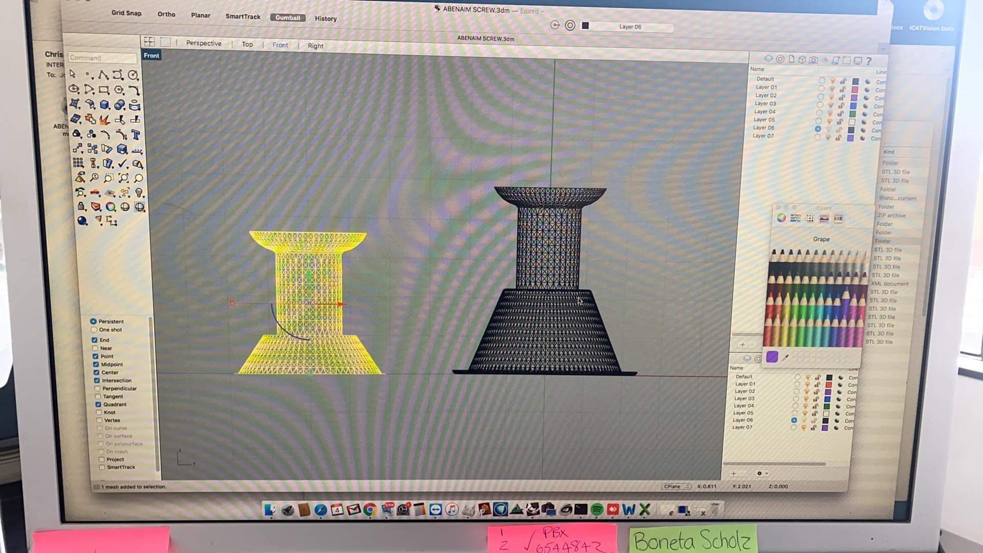
Jonathan Abenaim MUA’s and Powerball Screw now in iCam4D imetric library

There is a lot of focus nowadays on the connection between the screw and the MUA and top clinicians are recognizing this to be the most vulnerable part of full arch prosthetics.
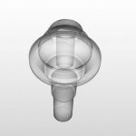
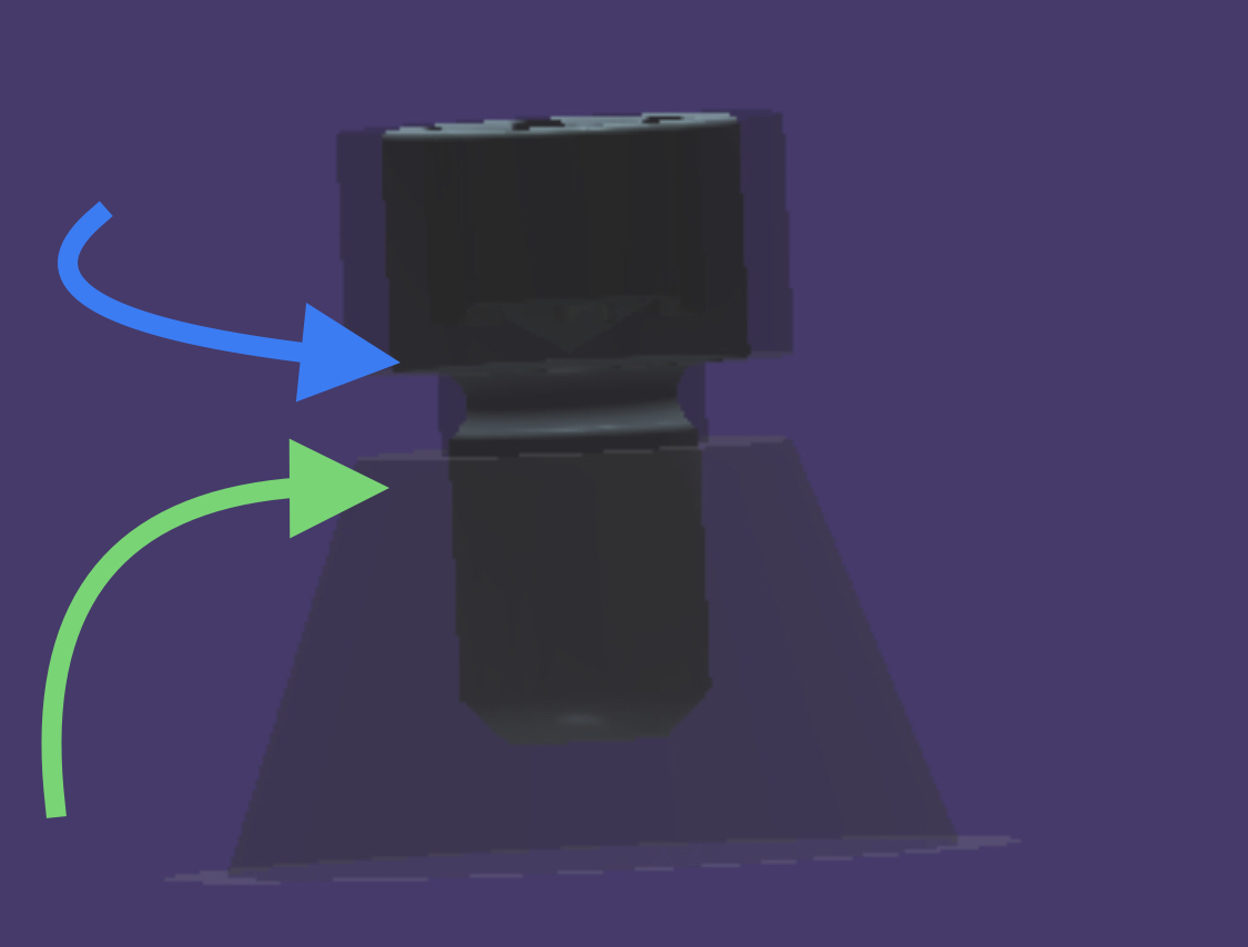
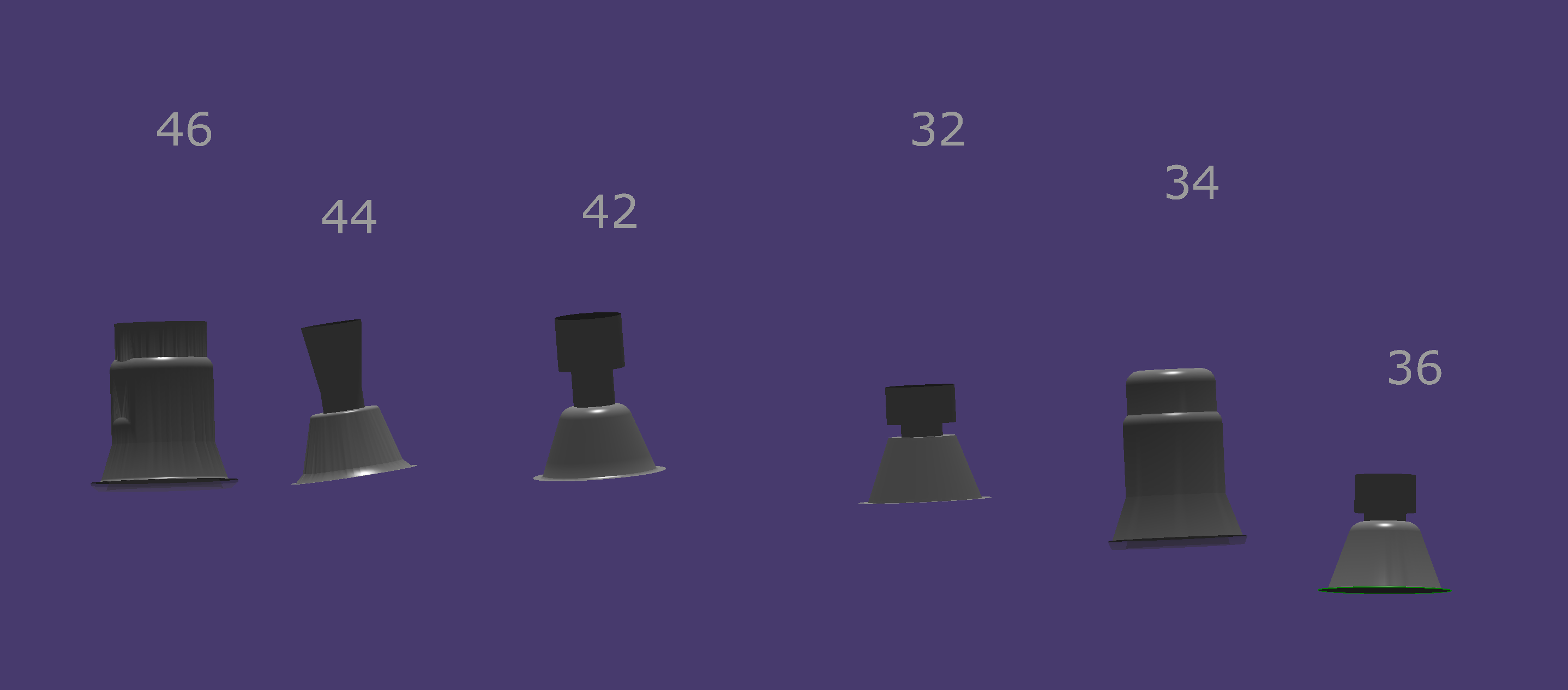
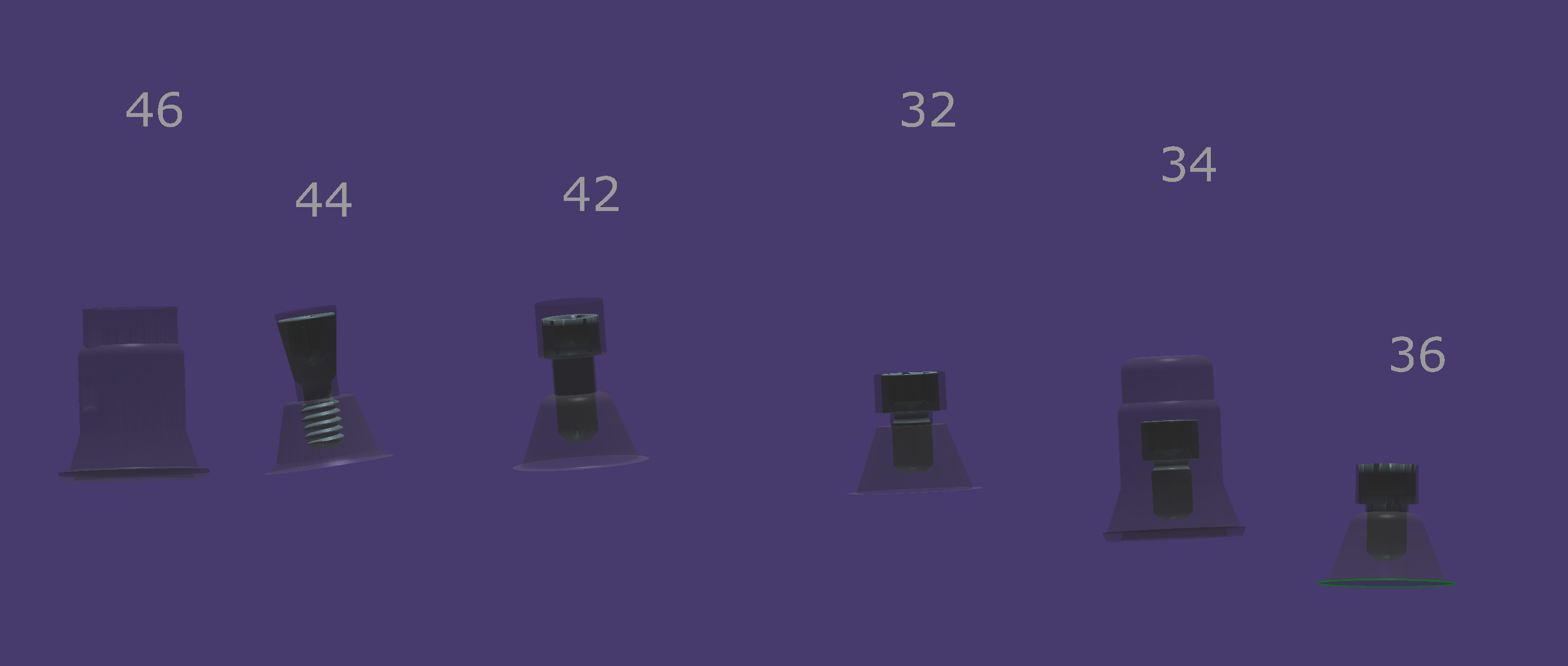
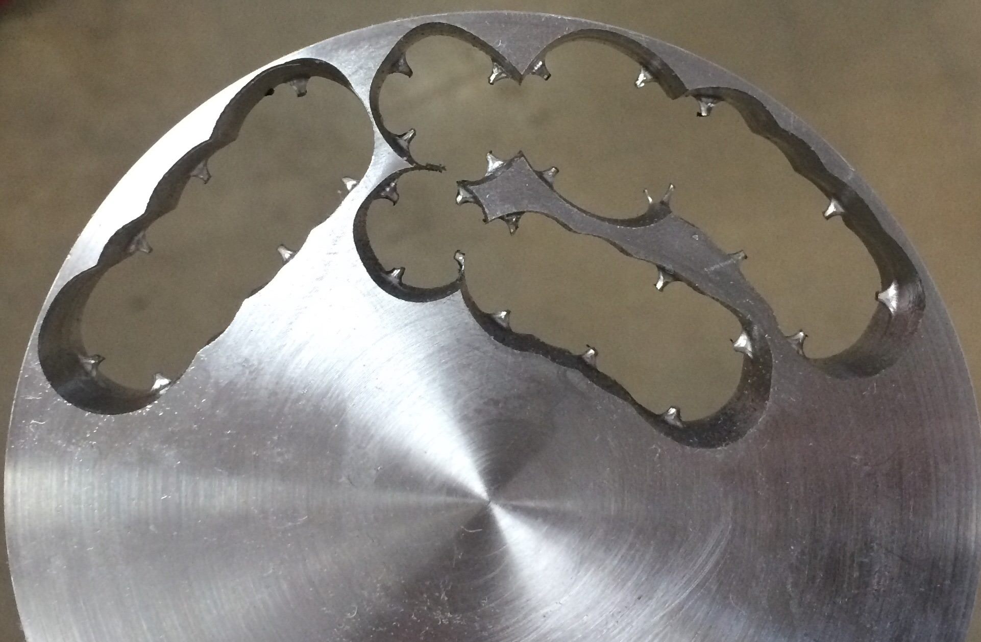
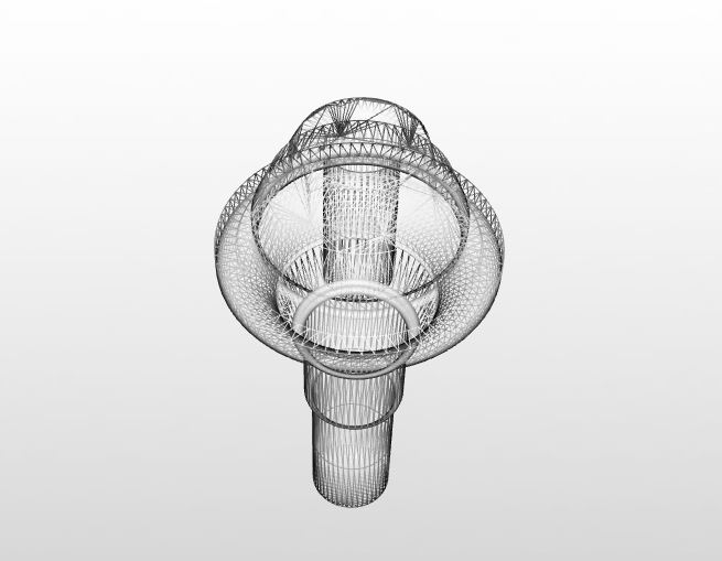
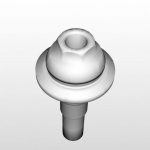
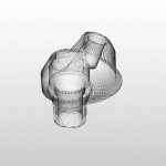
An issue to consider the space between the green and the  blue arrows on the following photo and how some have designed solutions around the small area that is prone to chirping or breakage during milling or printing

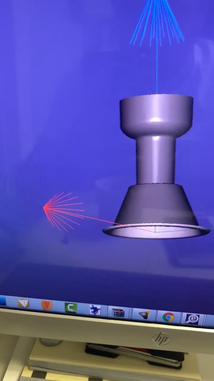
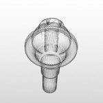
“The powerball screw by  Dr Jonathan Abenaim is one of a kind. Finally a screw designed to skip the tibase with the material in mind. It is rounded to provide gentle forces that are transferred to the body of the screw instead of the weak threads where the the screw is the weakest. It has the ability to be used in Zirkonia and pmma with no tibase. Its angle can be corrected up to 20 degrees. With our proprietary biaxial screw head the screw head is robust and cannot be stripped.”

video
play-rounded-fill
Powerball Design

For more information contact Smile Syllabus

Posted on Leave a comment

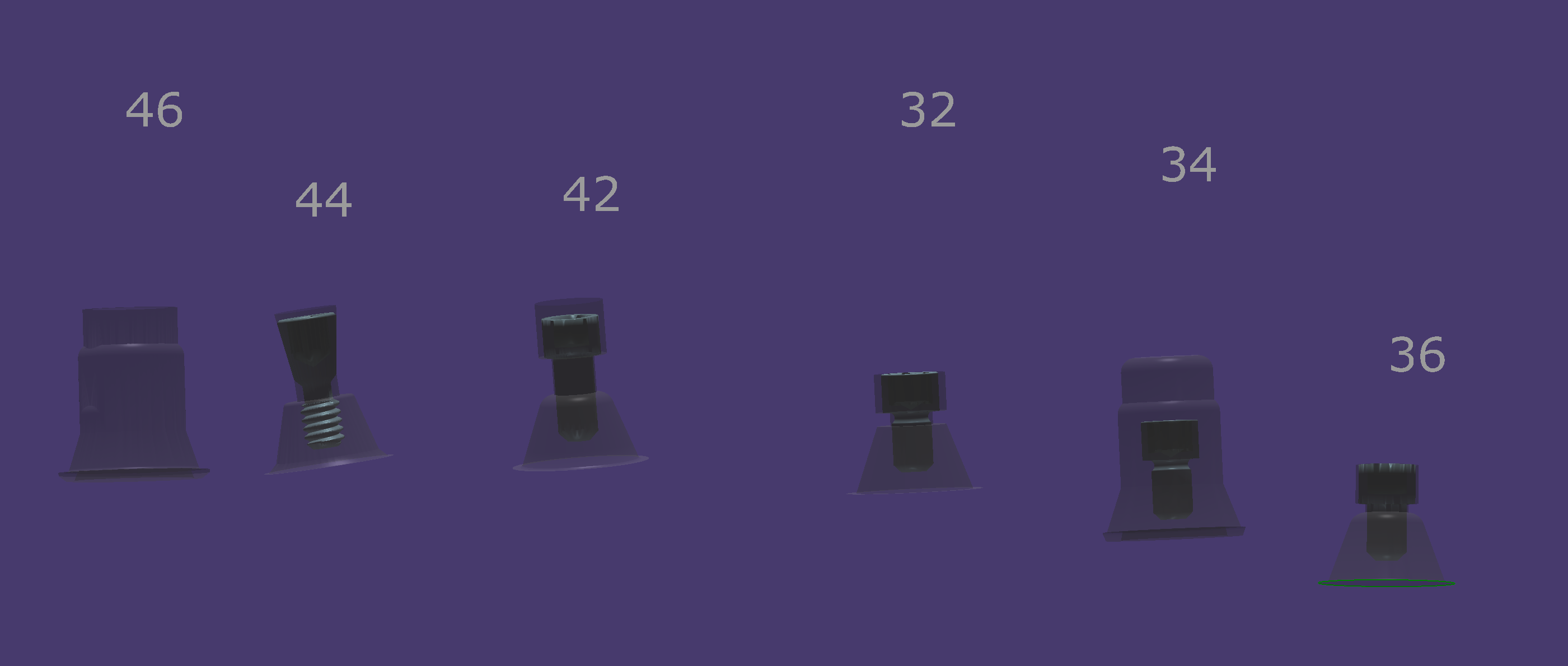
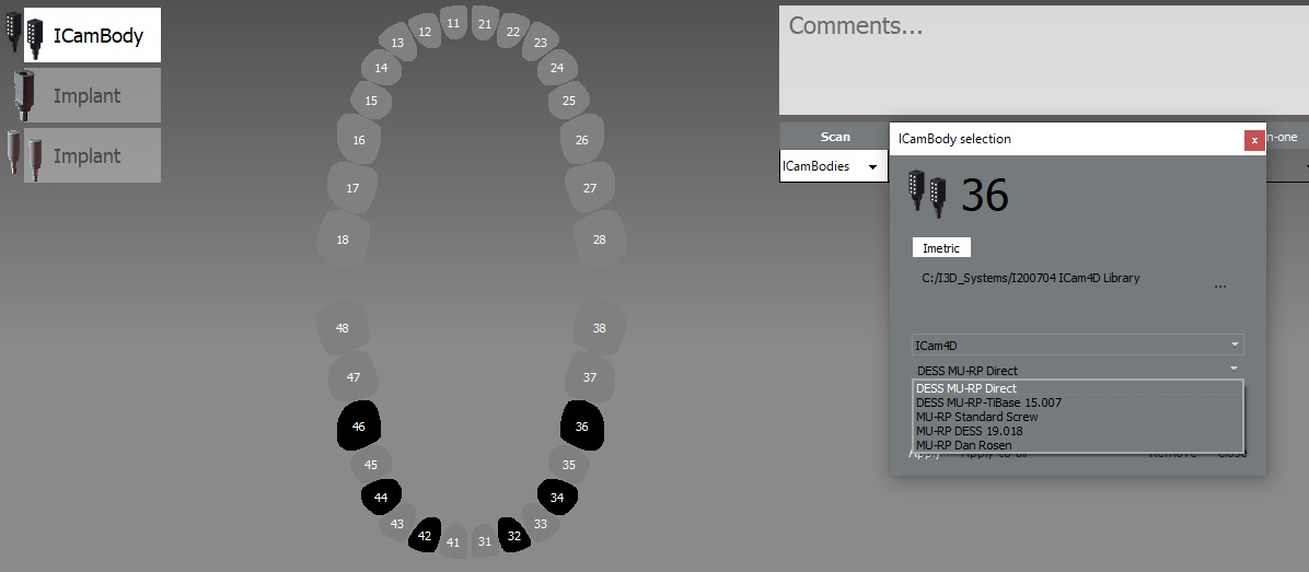
Screw Selection for Multi-Unit Abutment for iCAM photogrammetry

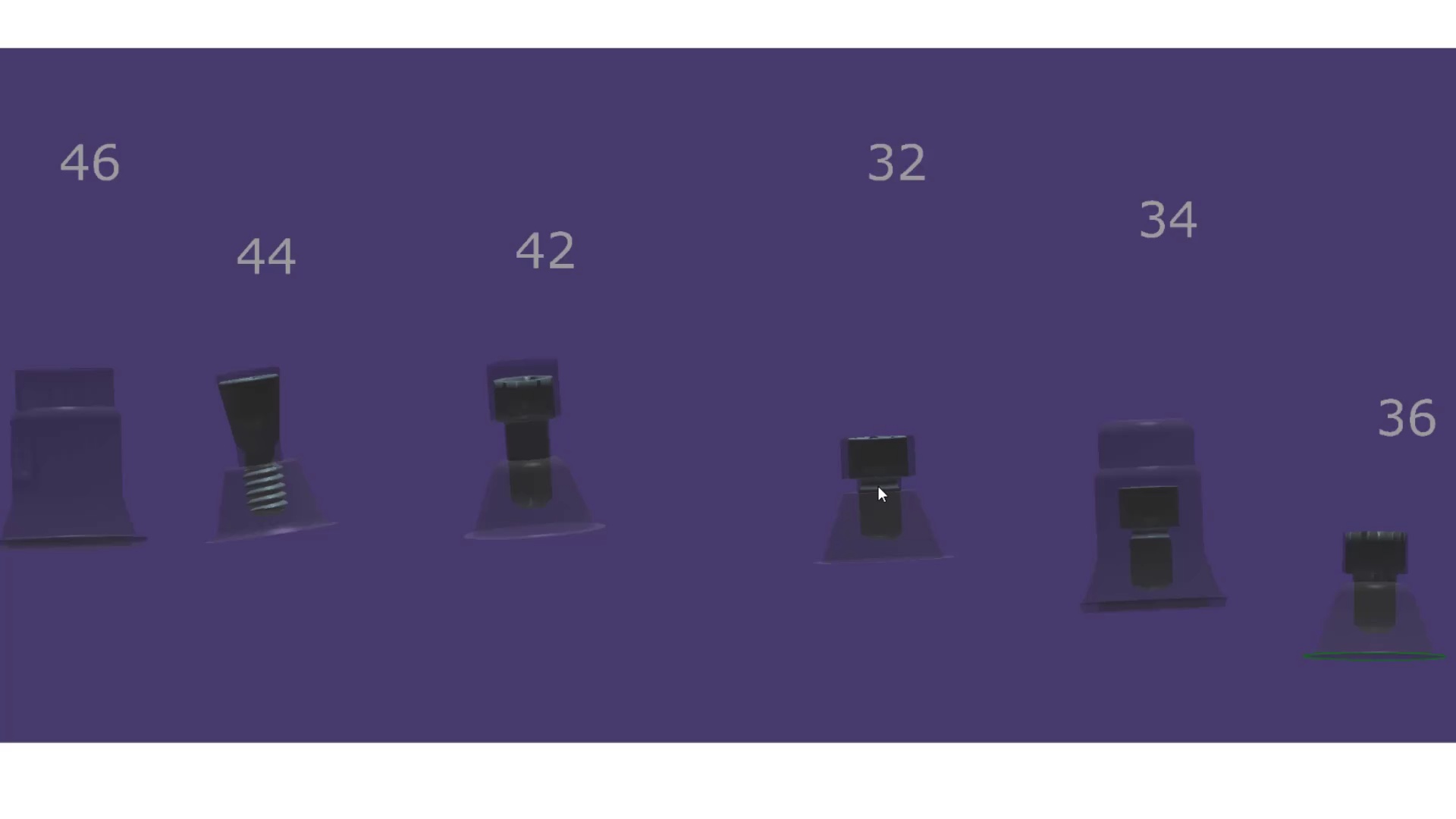
When setting up case in photogrammetry, you can select the type of screw you will be using for the prosthesis so that it gets incorporated into the design of the prosthesis.  There is a trend developing where doctors prefer to mill or print directly to the Multi-Unit Abutment and a standard screw won’t suffice.

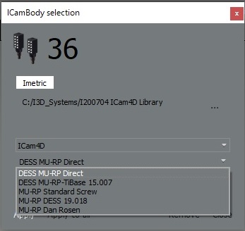
In Imetric’s ICam software you can chose which screw design you prefer which are often used to provide adequate spacing for the material and adequate length to engage the screw to the platform.  Properly labeling the  suprastructure at start up will provide the geometry you will need for the manufacturing.


video
play-rounded-fill
Implications of Screw Designs

Posted on Leave a comment

Full Arch Prosthesis – Current “Real World” Information


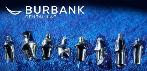
I am not one to place much faith in published articles from academicians. I usually draw my information from trusted colleagues and also a very reliable source, Mr. Andrew Sedler, from Advanced Technology Centers in Burbank California. He is in charge of manufacturing thousands of full arch restorations for clinicians and many other labs that outsource their manufacturing.
One of the things I always get a kick out of is whenever they do purchase technology or implement a process, they always have to do it with redundancy. What that means is that their machines can never go down for whatever reason, so they always purchase printers and mills by multiple sets. Interestingly, I was witness to them incorporating printers into the lab about 6-7 years ago and now they have a large wing dedicated to printing with over 20 machines for many different purposes.

I trust his judgement and always follow his recommendation and tested methods. When he says “do not bypass verification jigs, no matter what scanner was used”, I don’t even question it. He sees all the cases many entities can’t manage and he can manufacture any screw, prosthetic, abutment, etc… with their high end milling machines. In fact, it was on his word alone we decided to distribute the ICam4d by imetric.

I thought it would be a good idea to revisit full arch implant restorations with him and see what the state of the industry is like today and what he would recommend for the end users and patients. A very good perspective for a clinician to keep is how a simple mistake or misunderstanding can wipe away all the profit margins for a lab and even for the clinician. A simple example is if you have to correct an angulation issue on an abutment which can dramatically impact the costs of the lab work.
Here is the Q/A session:

“Hi Andrew, I am writing an article on full arches and would appreciate some info”

  • what % of the full arches that docs order from you are zirconia on tibases only at implant sites?
  • what % are on titanium bars?
  • what % are hybrids with acrylic?
  • what % are MUA vs Implant level?
  • what is the most prescribed full arch prosthesis now compared to 5 -10 years ago?
  • what % are soft tissue level vs bone level / mua level?
  • what would you do for yourself?
  • which one has the most failure rate?
  • how often does zirc framework break?
  • how much damage do you think people do to zirconia frameworks while trying to mill it to sharp corners of tibases?

Answers:

  1. MUA vs IMPLANT LEVEL : over 90% of upper arches will have MUA and 60 to 70 % of the lower arches will have MUA
  2. BONE LEVEL vs TISSUE: majority of implants (90% and up) bone level that requires MUA .
  3. The most failure rate in order is (all of these in respect to the material limitations ):
    • the traditional acrylic hybrid
    • composite hybrid next
    • zirconia monolithic
    • and the least breakage will be zirconia hybrid supported by metal frame
  4. Zirconia failure is around 4 to 5 %  (adding the internal lab remakes – i would say another 3 to 4 %)

The damage caused by adjusting the zirconia could be very considerable, especially around the access hole since those areas are thinner than the full teeth .  For myself i would restore zirconia over metal frame if my choice is hybrid, while removable bar overdenture will be a more predictable and more hygienic choice .

Posted on Leave a comment

ICam4D and DESS Multi Unit Abutments

it’s here! well technically it is crossing the atlantic. the icam4d’s are on their way.
separate from that, after i think a year long search, we have decided to carry the dess line of abutments because it is the one of the only lines that i can confidently say is well thought out and verified from start to finish. so you will be able to get a MUA to pretty much any implant line. some like bicons, if you choose to go that route will still have to be custom made and we can help you with that. But the vast majority of the implant lines and connections will be covered by this approach. Keith Goldstein is a tremendous resource and has agreed to provide us with a some important files and libraries. here is the significance of all this:
  1. if you want a fixture level impression vs MUA in those rare situations, you can still place a MUA and image that. The dess library can easily convert that information to the location of the fixture. you just need to make sure that you make note of the exact mua and collar height you used. the timing won’t matter as these are RP non-indexed abutments. that solves the number 1 request you folks make when looking at this.
  2. we will have all the libraries of the abutment from the margin and up available to you so you can pop them into the medit scan and easily identify the MUA in the mouth.
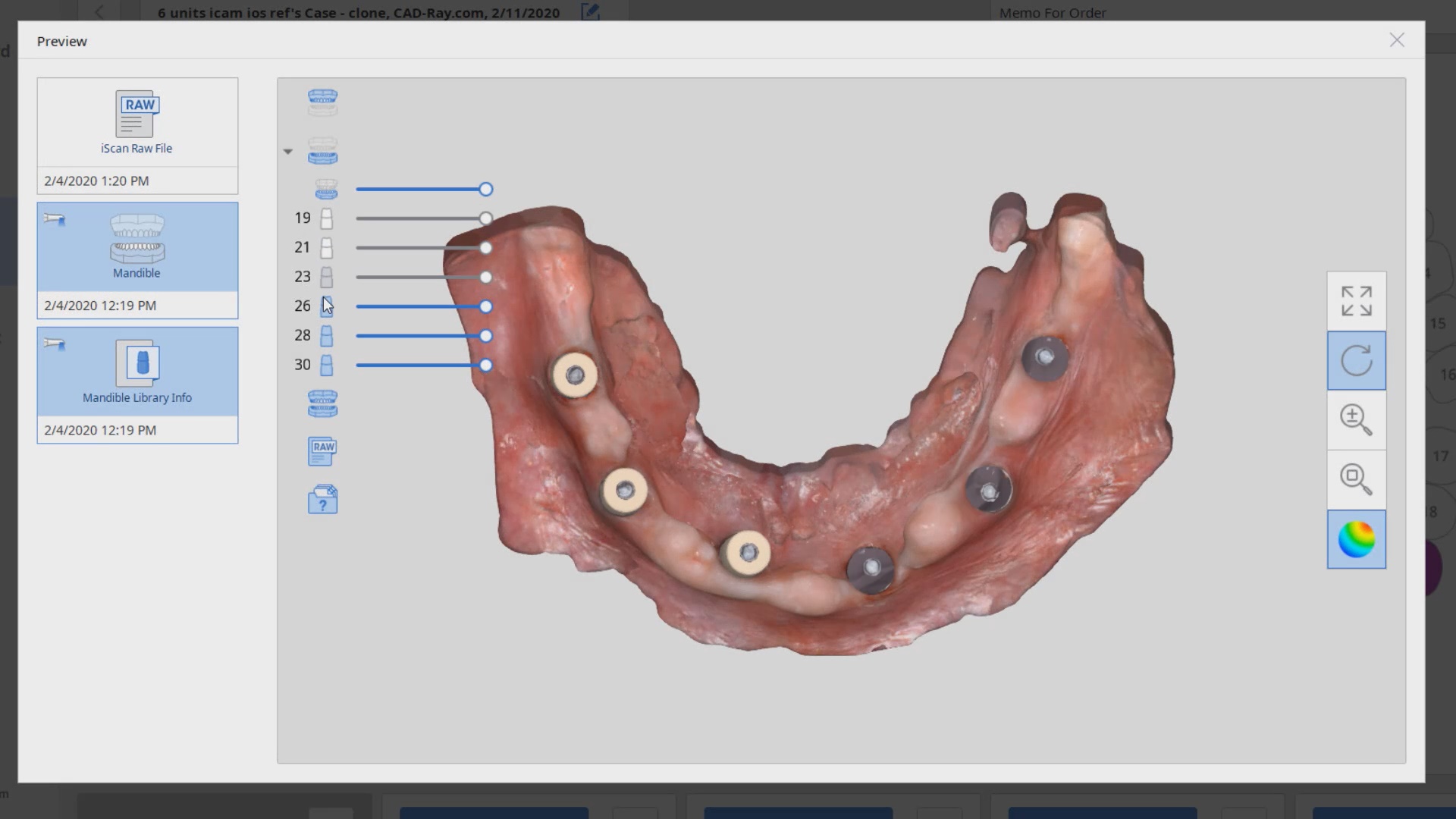
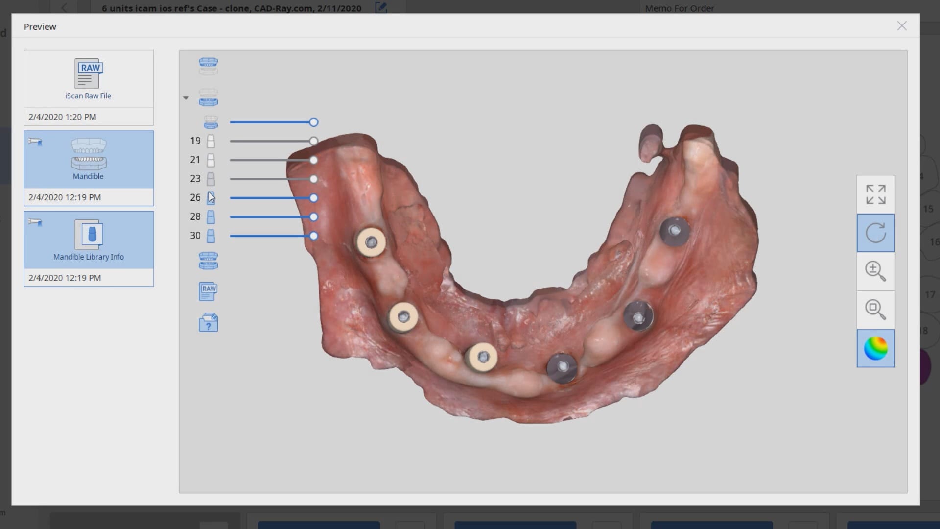
  3. for the process to work in the traditional way, you would have had to place the mua’s, place the scnflags, image with icam. take off scanflags, place cylinders, scan with ios. then take off cylinders and then place healing caps. NOW, you can place the MUA’s, place scanflags, image with icam. export the stl and import it into medit. take off scan flags, BYPASS the cylinders, and just start scanning MUA’s in the mouth. With the AI feature, you will readily identify the multi unit abutments no matter how bloody the field is and if parts of the margins are buried under tissue. Of course, in the situation where the implant is super deep and the mua can’t stick its neck out, you will still have the option of popping the cylinders on. you will know which route to go as soon as you seat the MUA after surgery or uncovery
Posted on Leave a comment

Multi Unit Abutment on ANY Fixture

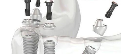
If you place enough implants, you may find yourself in need of a prosthetic part that just isn’t manufactured by anyone.  For example, you may have a hybrid case on Bicons and for some reason you wanted to restored them with Multi Unit Abutments (MUA) and photogrammetry, yet there are no parts manufactured for such an endeavor.  The problem is complex because a manufacturer needs to mass produce these parts and get them past regulatory matters.

Some have found a simple solution, which is to have the parts custom made specifically for the implant.  If they need the MUA part before the procedure, they just send a digital or physical model into a lab that can custom make the part.  The lab itself needs a prescription form on the lab analog.  Since it is custom made, you have direct input on how tall you want the height of the margin, how much  you want to displace the tissue, how much would want the restorative head angled, etc..

Most people will order a variety of them to address any situation on the same model and keep it in stock.  What’s important to realize is that from the restorative standpoint, all your CAD software needs to know is the location of your abutment margins.  It doesn’t care where fixture is and how the timing is lined up in the arch form. As long as it knows where the margins are, you can proceed with the design of the prosthesis.


Contact Andrew Seddler to send a digital or physical model and an Rx to get your custom made MUA’s

Posted on Leave a comment

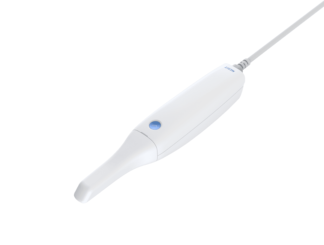
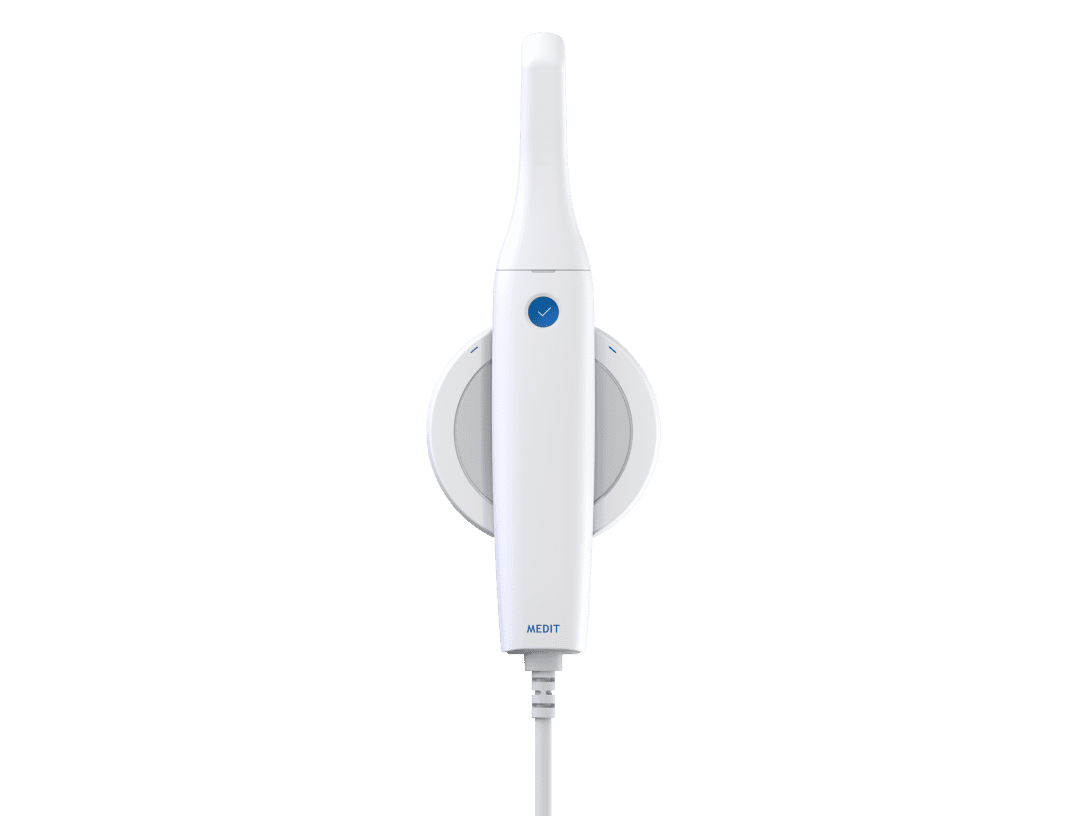
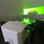
Mixing Photogrammetry and Intra-Orals Scanner by Medit i500

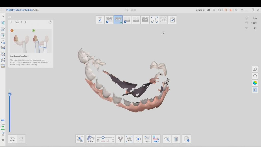
To date, the literature and research clearly points out that full arch scans with edentulous arches are prone to inaccuracies.  That’s because we have never had a way to measure and verify models while scanning. There are two features unique to the Medit i500, namely the reliability map and the artificial intelligent implant suprastructure identification system.  Individually, they do not provide much information with regards to accuracy, but if you understand how they work, you can utilize them to assess accuracy while you are scanning edentulous arches.

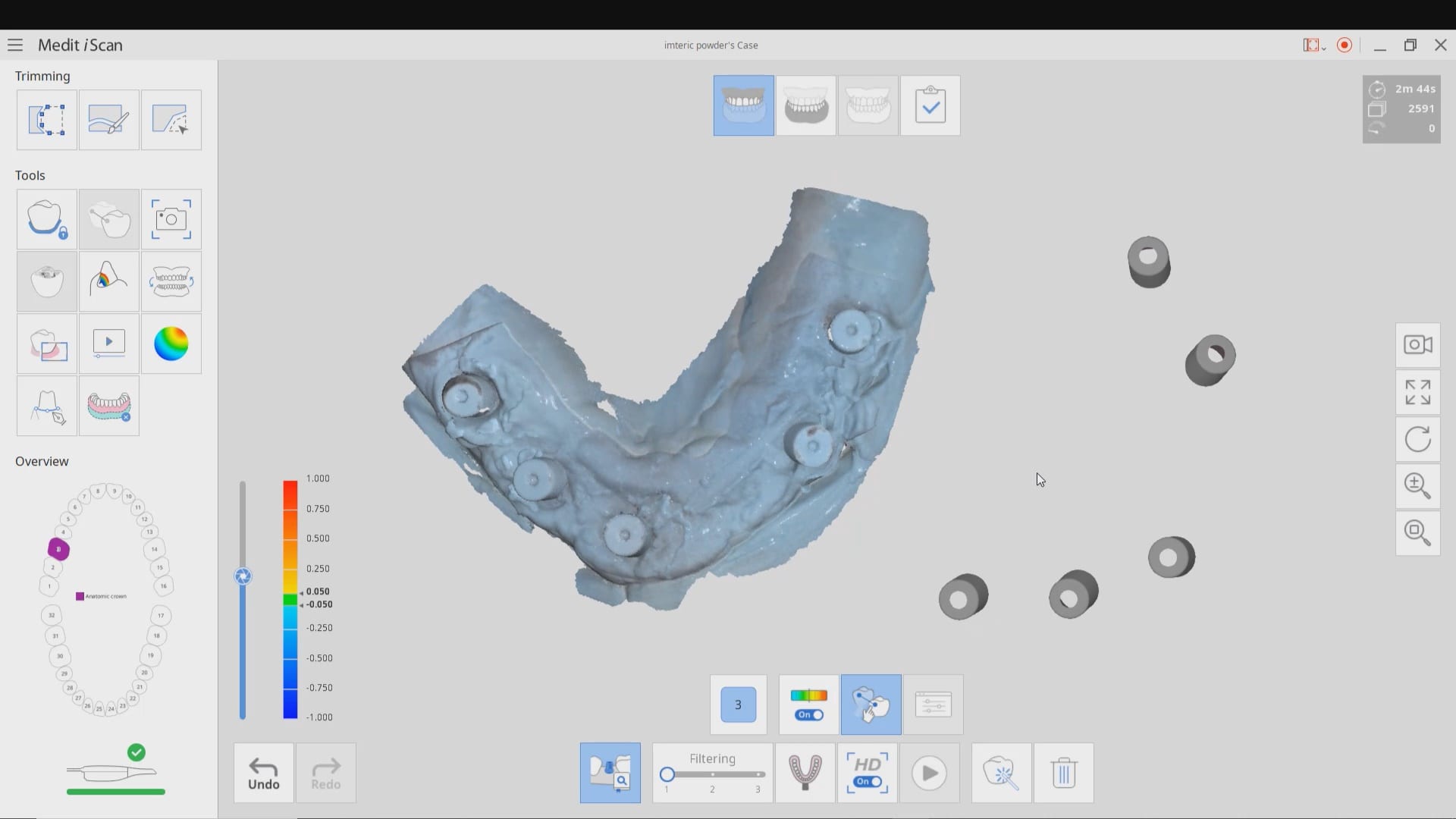
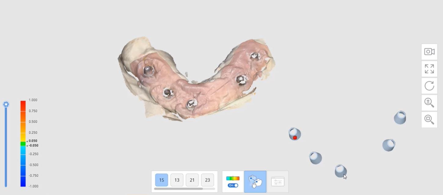
We proved the validity of this concept by utilizing these two features by incorporating a scan from the imetric Icam4D scanner and merging its data with the IOS to render a perfect match.  Details are posted for our users in the Imaging Implants Section of our tutorial liabrary

video
play-rounded-fill
Posted on Leave a comment

Using Photogrammetry to Validate the Accuracy of the Medit i500

Photogammetry has set the highest standard for full arch accuracy in digital dentistry for edentulous patients with multiple implant fixtures. An easy scan in under 15 seconds captures enough detail on scanbodies that help the software capture the location of the fixtures. Conversely, Intra-Oral Scanners (IOS) do not garner support for most of the literature that is currently published in dental journals.  Scan paths can dictate the outcome of 3D model and determine how correctly it replicates the intra-oral condition. The same scan can render a variety of results and models based on the user and the direction the scans are taken. Simply stated, the user is control over the final product.

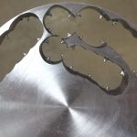
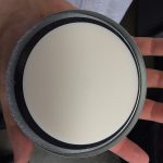
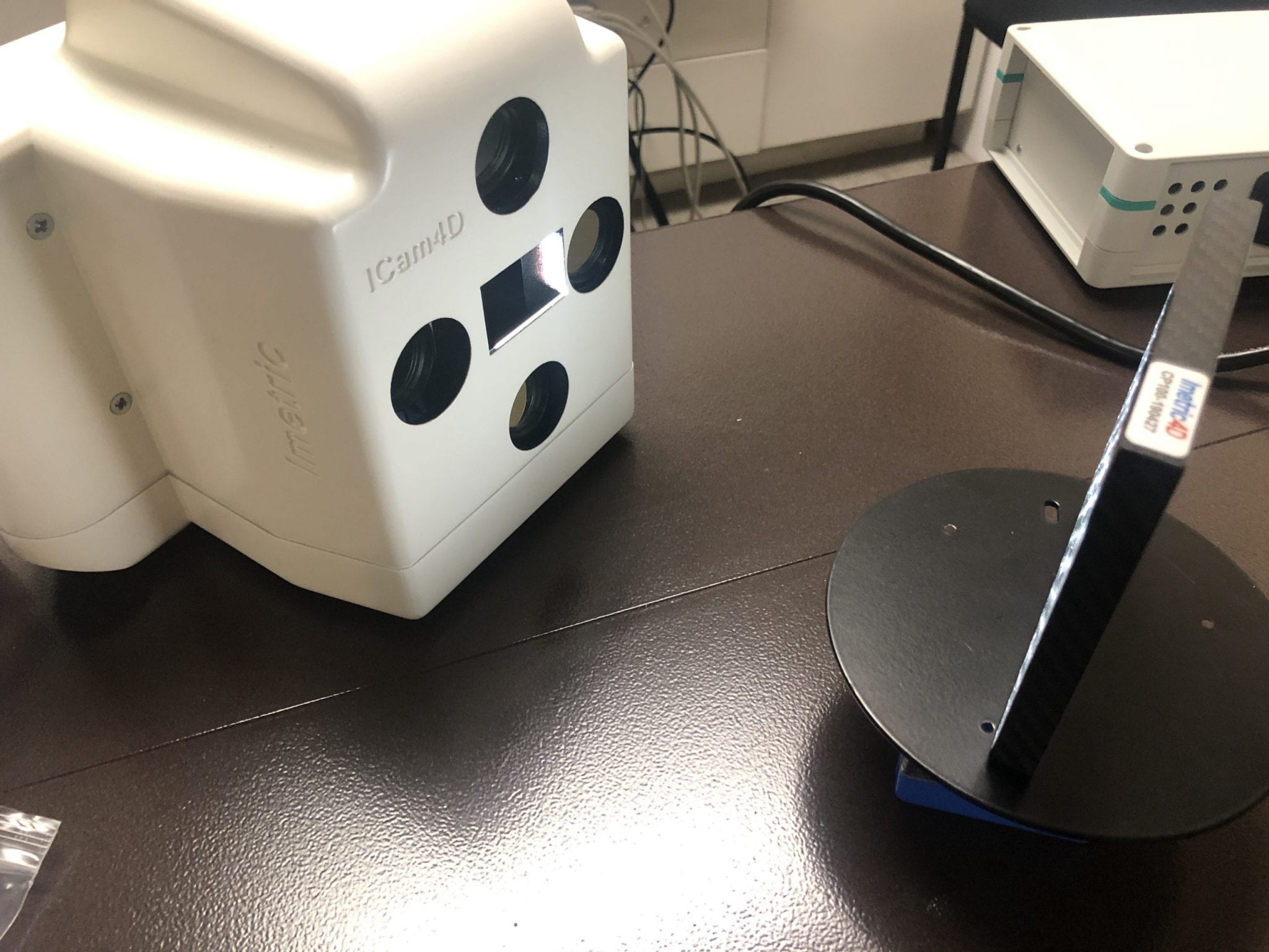
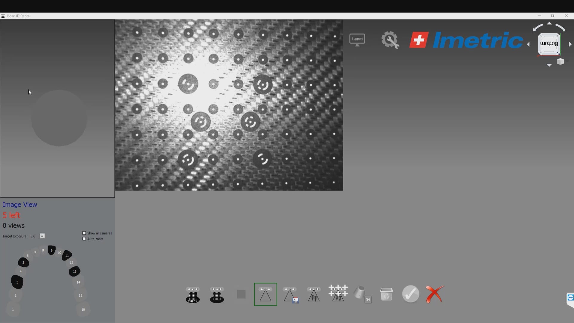
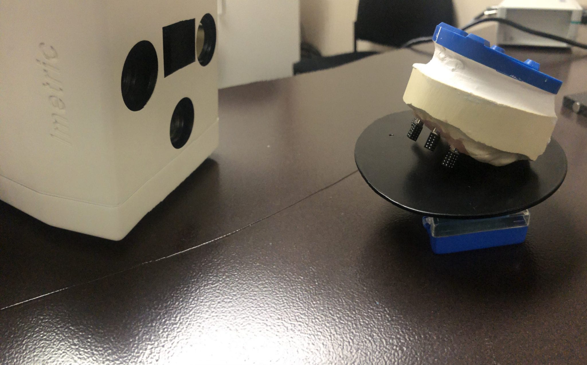
To use the ICam 4D scanner you must first calibrate the machine with a plate immediately prior to the intra-oral scan capture.  There are specific reference points that the camera and software recognizes and after you capture about a dozen landmarks, you are ready for an intra-oral scan

Calibration of the ICam 4D Photogammetry  Machine

video
play-rounded-fill
calibrate icam 4D


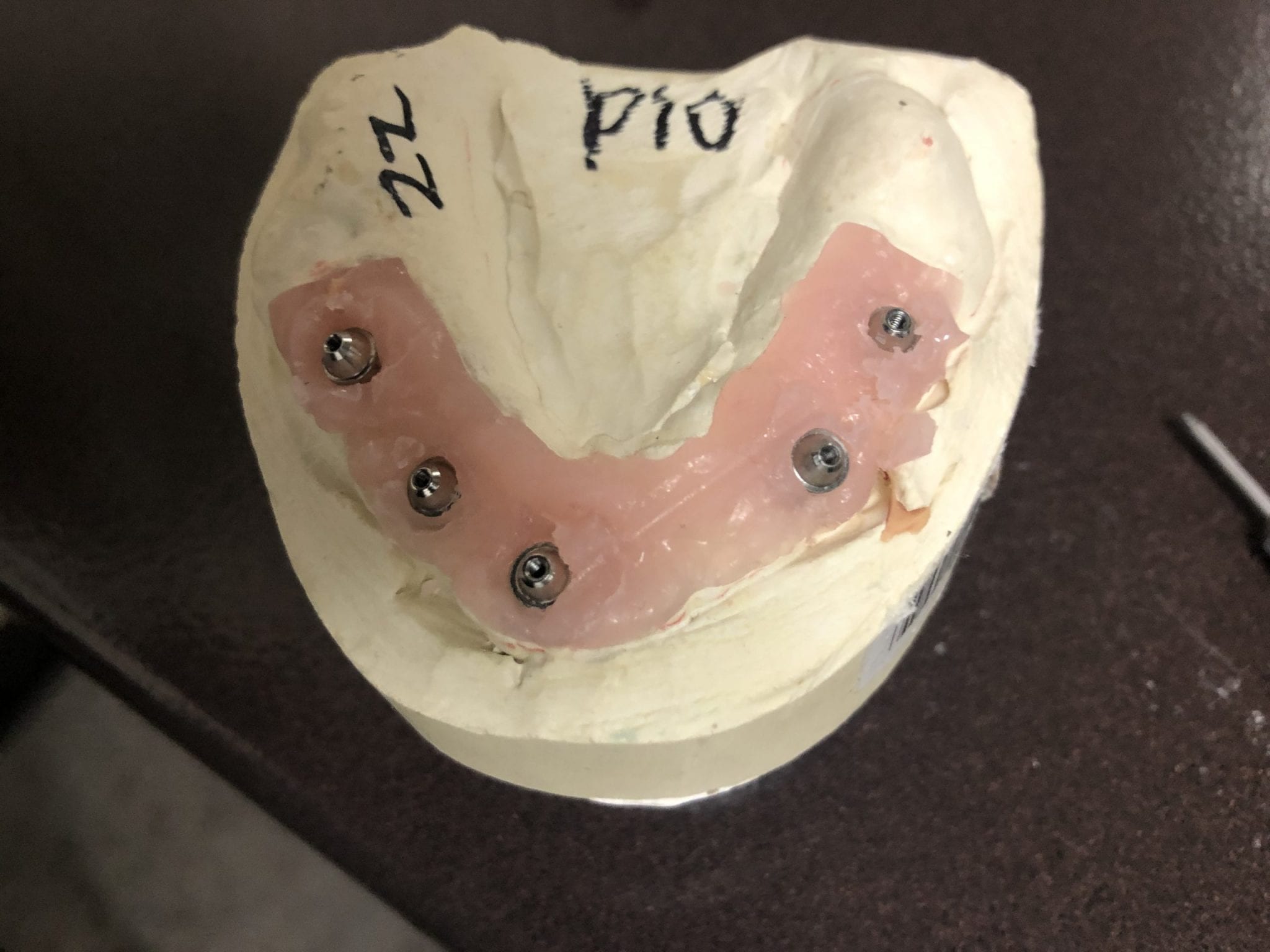
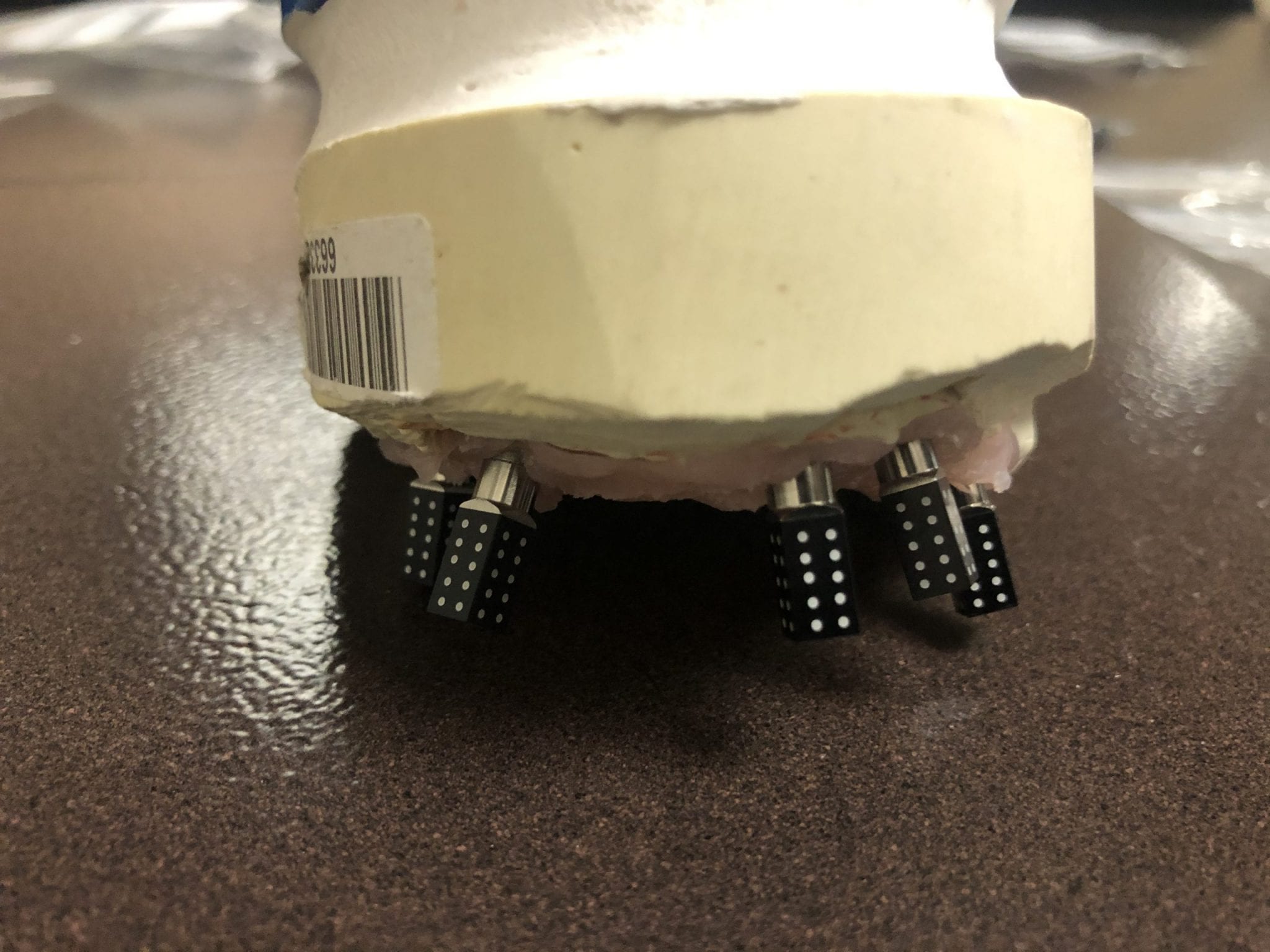
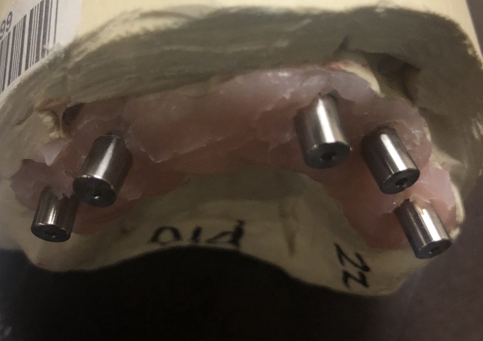
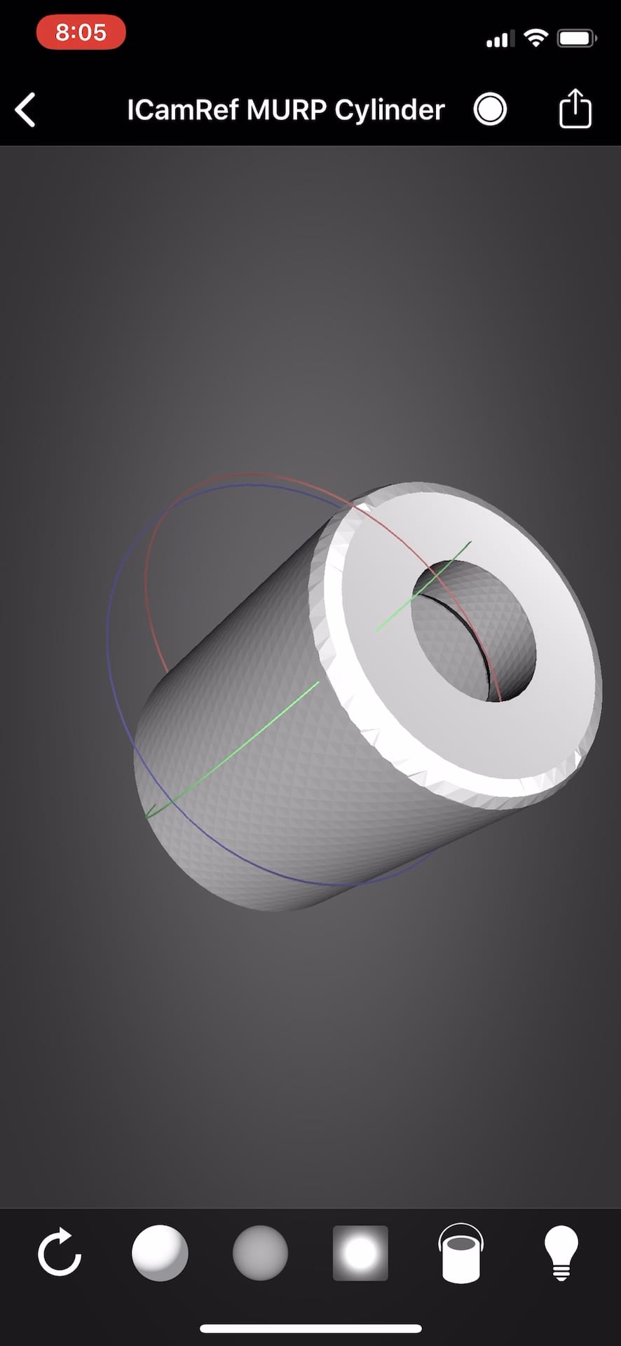
After the camera is calibrated, the patient, or in this demonstration case, the model with Multi-Unit Abutment analogs is mounted with ICam Reference Bodies that are shaped like dominos.  They can attach to the multiunit abutment or directly to the implant fixture (available soon in the USA).


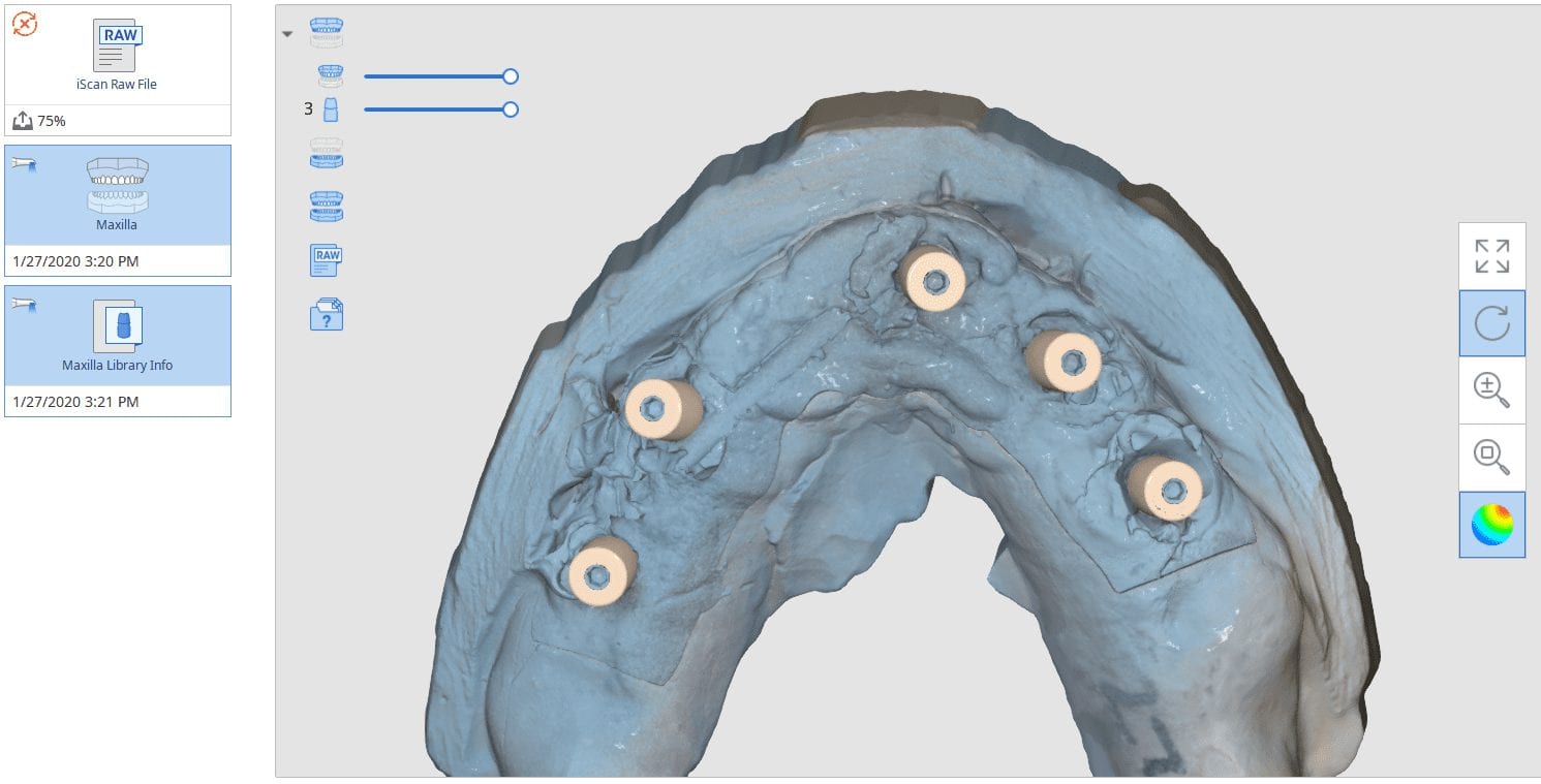
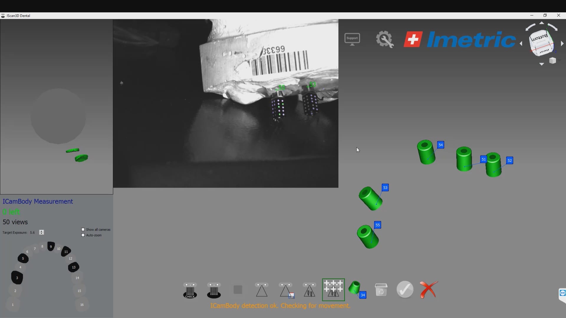
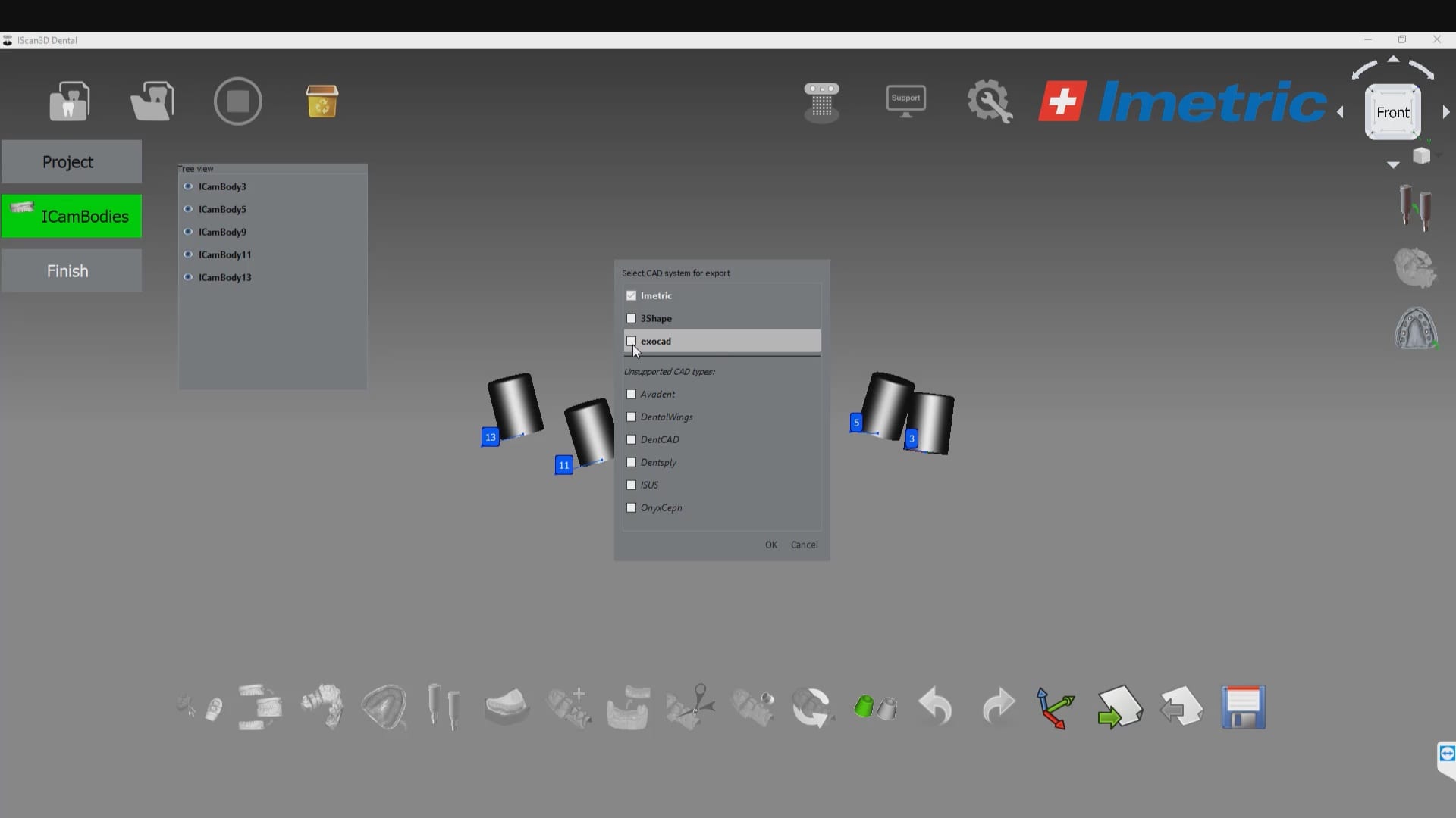
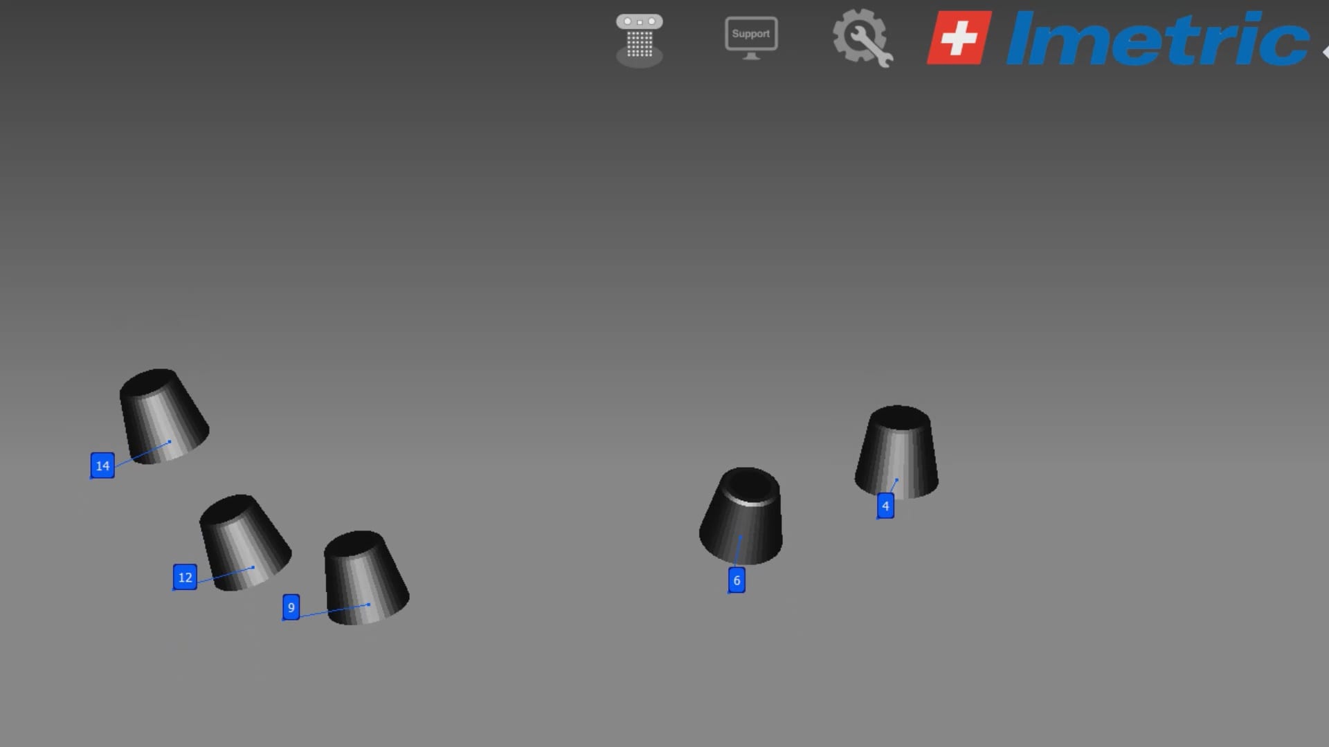
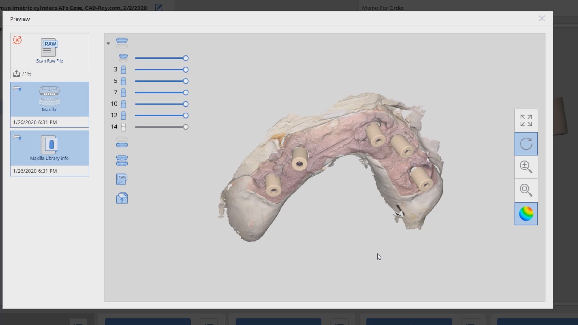
The markers are captured by the device in the software with multiple identification marks, ideally 10 marks on each scan post.  This data is then exported as an stl file that has all the locations of each cylinder preserved.  This whole process just takes minutes.  Most people just utilize this device for full arch impressions so they can bypass the verification jig for large cases.  Here, we use it to assess the accuracy of the medit i500 ios to provide cross arch accuracy if doctors follow our protocols for imaging, which utilizes the reliability map as a guide for imaging.  When then utilize the Artificial Intelligent Implant Suprastructure Identification Software to merge and evaluate the accuracy of the ios scan.

video
play-rounded-fill
measure implant icam scanbodies
video
play-rounded-fill
save the implant scanbody cyliners and their coordinates

There are a lot of ways one can introduce errors into a full arch scan with any ios, but the medit’s powerful features that include the reliability map and the AI tool separate it from all other scans that do not allow you to assess the accuracy of your scan while you are imaging.  You can only do so with the fabrication of a verification jig

video
play-rounded-fill
Medit's AI feature merges the IOS model with the photogammtry produced model
Posted on Leave a comment

Imetric ICam 4D Photogrammetry Meets the Artificial Intelligence Implant Suprastructure By Medit i500


video
play-rounded-fill
imetric icam scanbody alignemnt with medit i500 ios scan

video
play-rounded-fill
Stl of icam scanbody
video
play-rounded-fill
AI used to image imetric cylinders